"An IMU never lies about acceleration and never tells the truth about position; estimation is the art of reconciling the two."
A Careful Control Loop
Flight dynamics intuition is a concrete drones and aerial embodied AI skill. The page treats it as an embodied loop with named observations, actions, physical constraints, metrics, and recovery behavior.
This section develops flight dynamics intuition as a concrete embodied AI skill rather than a label. The core contract is: observe attitude, angular rates, thrust, drag, and inertia, command attitude or velocity through a stabilized controller, and judge the result with settling time, overshoot, and saturation.
For Flight dynamics intuition, check the earlier frame, control, and model chapters against the exact interface used here: state variables, timing budget, action limits, and evaluation panel.
Aerial agents pay for every bad decision immediately. They are underactuated, energy-limited, wind-sensitive, and often safety-critical. For Flight dynamics intuition, the decisive question is whether the loop can recover from the policy learns position control while hiding unstable attitude dynamics.
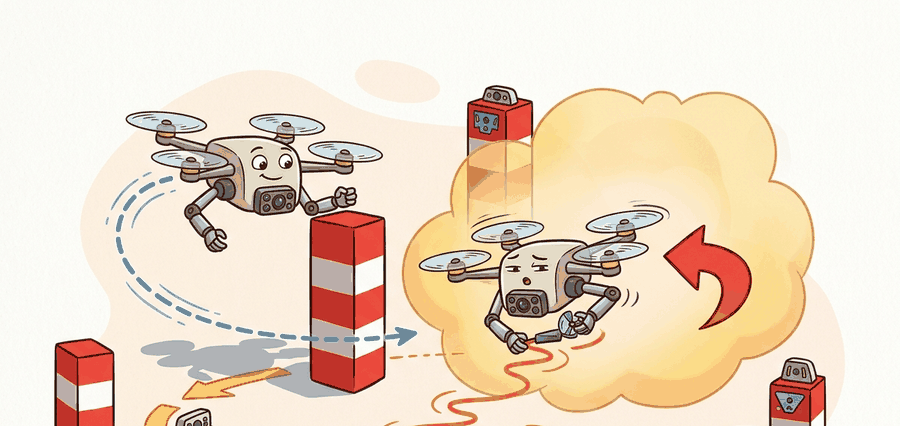
Figure 47.2.1 should be read as a flight-dynamics artifact map: motor model, rigid-body state, controller law, actuator limits, and logged residuals are separate boxes because each one can fail independently.
Theory
A drone has no direct sensor for position. It carries an inertial measurement unit (IMU) that reports body-frame acceleration $\mathbf a_m$ and angular rate $\boldsymbol\omega_m$ at high rate (200 Hz to 1 kHz), plus a camera that observes the world at a lower rate (20 to 60 Hz). Visual-inertial odometry (VIO) fuses the two. The estimated state is
$$\mathbf x = [\,\mathbf p,\; \mathbf v,\; \mathbf q,\; \mathbf b_a,\; \mathbf b_g\,],$$
that is, position, velocity, orientation (as a quaternion $\mathbf q$), and the accelerometer and gyroscope biases $\mathbf b_a, \mathbf b_g$. The biases are part of the state because they drift slowly with temperature and time, and an uncorrected bias integrates into runaway position error.
The IMU measurement model removes bias and noise before integration: $\mathbf a = \mathbf a_m - \mathbf b_a - \mathbf n_a$ and $\boldsymbol\omega = \boldsymbol\omega_m - \mathbf b_g - \mathbf n_g$. Integrating once gives velocity, twice gives position. Doing this naively between every camera frame is wasteful, so modern VIO uses IMU preintegration: the relative motion between two camera frames is precomputed as a single pseudo-measurement (a delta in position, velocity, and rotation) that does not have to be recomputed when the linearization point changes. This is the trick that makes tightly coupled visual-inertial optimization run in real time.
There are two dominant architectures. Optimization-based VIO (VINS-Mono, ORB-SLAM3) keeps a sliding window of recent frames and solves a bundle-adjustment problem that jointly refines poses and landmark positions; it is accurate but heavier. The MSCKF (Multi-State Constraint Kalman Filter, used in OpenVINS) keeps a window of past camera poses in the filter state and marginalizes each landmark after it leaves the field of view, giving filter-like constant-time updates with good accuracy. The choice is a compute-versus-accuracy trade, not a correctness one.
Flight dynamics failures should be traceable through motor command, thrust model, attitude estimate, angular-rate error, position error, and controller saturation. That chain distinguishes a weak controller from a bad mass estimate, poor motor calibration, delayed IMU stream, or impossible trajectory.
Worked Example
The reason VIO needs the camera at all becomes obvious once you integrate the IMU alone. Here a stationary drone reads a tiny constant accelerometer bias of 0.05 m/s$^2$. We dead-reckon over 0.1 s at 100 Hz: integrate acceleration to velocity, then velocity to position, and watch the position error grow quadratically even though the vehicle never moved.
# IMU dead reckoning: integrate acceleration -> velocity -> position.
# A small uncorrected bias makes pure inertial position drift fast.
dt = 0.01          # 100 Hz IMU
steps = 10         # 0.1 s total
a_true = 0.0       # drone is stationary
a_bias = 0.05      # m/s^2, unmodeled accelerometer bias

pos, vel = 0.0, 0.0
for k in range(steps):
    a_meas = a_true + a_bias       # what the IMU reports
    vel += a_meas * dt             # integrate accel -> velocity
    pos += vel * dt                # integrate velocity -> position

print(f"after {steps*dt:.2f} s of dead reckoning:")
print(f"  velocity error : {vel:.4f} m/s")
print(f"  position error : {pos:.6f} m")
# Extrapolate the quadratic drift to 1 s and 10 s.
for T in (1.0, 10.0):
print(f" projected position drift at {T:>4.0f} s : {0.5*a_bias*T**2:.3f} m")Expected output: a velocity error that grows linearly and a position error that grows quadratically with time. The projected drift is the evidence field that matters: if your VIO loses camera tracking for even a few seconds, this is how far the estimate can wander before visual updates resume.
For Flight dynamics intuition, the hand-built record exposes the flight fields; PX4, ROS 2, MAVLink, gym-pybullet-drones, Aerial Gym, and safe-control-gym should preserve the same schema.
Practical Recipe
- Write the skill contract: observable variables, action interface, metric, allowed recovery actions, and stop conditions.
- Build the smallest baseline that can fail in an interpretable way.
- Run the maintained library version with the same inputs, scenarios, and metric code.
- Add one perturbation aimed at the expected failure: the policy learns position control while hiding unstable attitude dynamics.
- Save one artifact containing config, seeds, logs, summary metrics, and two representative traces.
VIO drift in feature-poor environments is the dominant failure. White walls, fog, darkness, water surfaces, and fast rotations all starve the camera of trackable features, so the estimator falls back toward pure IMU dead reckoning and the position drifts exactly as the worked example shows. The plot can still look smooth because the filter keeps reporting a confident pose; the tell is rising estimator covariance and shrinking feature count, not a visible jump. Monitor tracked-feature count and innovation magnitude, and trigger a hover-and-hold or descend-to-known-mat behavior before the drift accumulates into a wall.
A robotics team using flight dynamics intuition should log not only final success, but intermediate observations, chosen actions, controller status, and recovery events. The logs reveal whether the method is solving the task or merely passing the easiest episodes.
When flight dynamics intuition feels abstract, ask what would be different in the next frame of video, the next robot state, or the next safety margin.
For Flight dynamics intuition, treat frontier claims as hypotheses until they expose enough detail to reproduce the result: data boundary, embodiment, controller interface, evaluation panel, and failure cases.
Can you name the observation, state estimate, action, success metric, and most likely failure mode for flight dynamics intuition? If not, the system boundary is still too vague.
Flight dynamics intuition becomes robust when the chapter separates three claims. The conceptual claim explains why the skill should work. The systems claim explains which interface changes. The evidence claim records which same-panel metric would convince a skeptical builder.
For Flight dynamics intuition, keep flight physics, airspace constraint, battery state, timing, wind, and safety monitor inside the evidence artifact rather than in a post-run explanation.
| Tool or Library | Role in the Topic | Builder Advice |
|---|---|---|
| gym-pybullet-drones and PX4 SITL | Main practical route for Flight dynamics intuition | Use it after the baseline contract is explicit and keep the same artifact schema. |
| ROS 2 logs | Interface and timing evidence | Record observations, commands, controller status, and verifier events together. |
| Same-panel evaluation script | Construct-matched comparison | Compare methods only when metrics are co-computed on one scenario panel. |
For Flight dynamics intuition, the coordinate-frame link is operational: every artifact should name frame, timestamp, units, safety constraint, and the downstream evaluator that will consume it.
Create one scenario for Flight dynamics intuition, run the baseline and the gym-pybullet-drones and PX4 SITL route on the same inputs, then label each failure as perception, state, planning, control, timing, data coverage, or evaluation.
When Flight dynamics intuition fails, do not collapse the whole method into one score. Assign the failure to a subsystem, rerun one perturbation that isolates the suspected cause, and keep the trace as a reusable diagnostic case.
Section References
Core references for Flight dynamics intuition: MuJoCo, Drake, ManiSkill, ROS 2, MoveIt, CARLA, nuScenes, Waymo Open Dataset, tactile sensing, locomotion, manipulation, and AV evaluation literature.
Use these sources to verify dynamics, contact, sensors, planning, embodiment constraints, and evaluation panels.
Flight dynamics intuition is useful when it makes the perception-action loop more reliable, not when it merely adds a more impressive model name.
Design a same-panel experiment for Flight dynamics intuition. Specify the scenario set, the baseline, the gym-pybullet-drones and PX4 SITL library route, the metric computation, and one perturbation that targets this failure: the policy learns position control while hiding unstable attitude dynamics.